Sunday, May 4, 2014

Mounting Engine

Hours 89
Total Hours 851

I had a good two weeks at the rig without too many problems so I had some time to study up and plan the things I needed to work on to get the engine mount, landing gear, and engine mounted during my April building session. 

The first order of business was to finish up my wiring as best as I could before mounting the engine mount and landing gear as that would raise the fuselage about 12" higher. I wired up my P-Leads to the ACS ignition switch. These are actually wires that ground out the magnetos in the off position. The switch also grounds out the right mag in the start position so the impulse coupled mag on the left can start the engine in a slightly delayed timing so the plug will fire on the down stroke. I also wired the P-Leads to the Dynon Skyview  Network so that it can give me the engine RPM on my effis. I used the solder sleeves to connect the shields.

Since this is all a little confusing so I double checked my P-Leads to make sure they were grounding in all the right positions of the ignition switch. We wouldn't want the mags to be hot when they are not supposed to be hot! After confirming I had wired everything right, I re-installed the ignition switch to the panel.

I also decided to wire my panel dimmer light and my baggage compartment light to a isolated circuit coming off the battery. I used a 10 amp inline fuse for this as it came off the battery. (Not Pictured) I didn't want to have to turn on my master switch just to load some baggage and get ready to fly. Then I started a two or three day process of cleaning up my wire runs behind the panel and installing plate nuts and adel clamps to secure all the wires. I used about 1000 cable ties bundling wires only to cut them off and start over when things didn't look right. This process was very frustrating! I had to walk away many times and calm myself down. I believe my wiring runs are my weakpoint on this whole project! I wished I could just start over but I know I cant.

After a few days of fighting the whole process, it gradually started looking better. I originally planned to have all my wires under all the sub panels so I could take the entire harness out if I ever needed to. In reality, that is probably a pipe dream as there are so many wires connected to so many things. I could still do it if I had to but the big problem is the shielded wires! They would be tough to splice. 
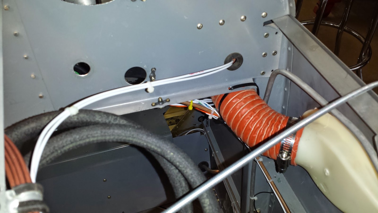
These two P-Leads are the only ones passing thru a hole but I wanted to keep them away from my audio wires. I installed the scat tubing from the vents to the Stein vents on the panel. This was not nearly as hard as I thought it would be. It was nice to get a break on something after the wiring headache! 

Moving on to my fiberglass canopy fairing, I peeled the peel ply off and put a application of Super Fill on and let it cure. I sanded that down smooth.

I had layed the piece up earlier from 8 layers of cloth with some micro between the 5th and 6th layers to make the transition. All this was layed up on the canopy and fuselage on a layer of packing tape that had 5 coats of mold release wax. The part popped right off and I was thrilled! I had been dreading fiberglass work for a long time  and it was great to accomplish this. Of coarse there is a ton of work left to do on this part!

After trimming up the part, I shot it with primer, found all the pinholes, sanded, thinned some Super Fill and filled pinholes, sanded, shot with primer, and repeated this process about 5 times! It looks great but I still have a few pinholes! I'm studying about these pinholes and will come back to this.....but I am so thrilled with this part! It seals so close all over and fits so well! I cant tell that the canopy was a little higher than the fuselage or the side was a little inset!

I ran the heater cable according to the plans. I bought the stainless steel door from ACS so the large hole will need a B-nut and not the z-bend Vans recommends. 

I installed the sensor manifold, 60 amp ANL fuse, battery ground cable, and several firewall plugs. I sealed everything up with 3M Fire Barrier+ 2000. 

The throttle and mixture holes were made by the previous owner for a carb engine so I left them there and will try to utilize them where they are without putting more holes in the firewall. ( I later learned that the best place to run these cables is underneath the sump of the engine because I'm using the Vetterman 4-pipe exhaust set up. This worked great with the holes where they are) Also as you can see, the fuel fitting is a few inches lower than the fuel injected plans but I believe it will work fine. Not having the crossover exhaust is really going to work in my favor.

I installed the platenuts for the manifold pressure hose then clamped the hose on with the adel clamps in the firewall forward kit. I also installed the second firewall pass thru on the left side. I then lifted the fuselage up and took off the stand that I had built out of 2x6's....Its time to get that mount on!

I mounted the engine mount. It was difficult as the holes were already drilled for the previous "nose dragger" mount that I had taken off. But both mounts are designed for the same hole pattern. The bolts were tough to get in. Luckily I had some old bolts that I could use to help line the holes up. I torqued them to 190 inch pounds and installed the castle nuts and cotter pins. These six little bolts are mighty important as they will have 180 horses pulling on them!

 I installed the wheels on the landing gear legs, they were already assembled by the previously builder but I took them apart and repacked the wheel bearings. The big surprise was how hard the  left leg was to get into the engine mount socket! This turned out to be an all morning fight! I removed it several times and cleaned more and more powder coat off the leg until it finally gave up and slid into place. I coated the inside areas with wheel bearing grease to inhibit corrosion. I guess it is better to be tight than loose as the one bolt controls the amount of toe in of the wheels. I fought that one bolt for a couple of hours before I realized the inside hole has to be match drilled to the leg and outside hole! After I match drilled it, it was still tight but I got it in. The plans call for a nylock nut but I have ordered an all steel locking nut to put here. The red tape is a reminder that the nuts need to be replaced and torqued. Now she's standing tall! 

I really lucked out getting my engine ready to mount. I had read of others that battled the "Dutchman" as my daddy would have called it, for ever! It is a 1/4" pipe plug with an Allen head hole. I heated it a little and it broke loose right away! I installed the bushing and the AN822-4 elbow. This is where my oil separator will return the oil to the crankcase. I wanted to get this done before the engine is mounted. 

Installed the oil temp fitting with a new crush washer and safety wired it. The breather fittings were left as was from the previous installation. The mechanical RPM cap is installed and I later safety wired it. There is a steel AN823-4 just under the piece of duck tape. This is where the previous install connected the oil pressure hose. Vans plans call for a different place to get oil pressure and to use a  fitting that is restricted. I could not get this  "Dutchman out!" I finally ordered a steel flair cap to cap it with and installed Vans restricted fitting as per plans.

I checked a rechecked the plans and various build sites to make sure I didnt need to do anything else before mounting the engine. I reread the write ups on mounting the engine and Vans instructions. I raised the tail. 

I layed out the Lord mounts and studied SK-90A. I got my lift all ready. I ignored all the suggestions to get some buddies together to help me and decided to do it alone the next morning. If it was too difficult, I could get my wife, Nancy, to help. I usually work best alone so I can take time to think things out. I got up early the next morning and mounted the engine!

I didnt take any pictures. I took my time. I lifted the engine with the lift and maneuvered into position to get the upper right bolt in first. This bolt took the longest as I didnt know how to maneuver the engine to get the results I wanted. I finally got the bolt in and tightened it. The upper right bolt took some time but I had a little experience now. The lower right bolt popped right in and surprised me! I did have to loosen the top two bolts first. I had to manhandle the last bolt but it didn't take half the time the first bolt did. What helped me the most was inserting a smaller bolt with a flat end on it (no threads) and feeling to see which way the biscuits needed to move to line up with the engine. It took me three hours to have the engine mounted. Half of that was torquing the nuts and installing the cotter pins. I torqued the nuts until I felt them bottom out just like Vans instructions describes.

Needless to say, I am thrilled! I know I have got a long way to go getting everything hooked up, but my project really looks like an airplane now!

I decided to spend some time trying to figure out where I want to mount and run fuel lines, engine controls, and electrical connections. here I am looking at the fuel servo deciding where to mount the red cube fuel flow analyzer.
I reconfigured the spider to mount on the right side of the engine. I am replacing the injector lines later after finding a cracked nut on one of the lines. 

 I installed the transducers for the fuel and oil pressure and wired them into the Dynon EMS.

 I installed the manifold pressure line to the firewall. I used a bulkhead fitting. I also installed the Anti-Splat oil separator to the firewall.
The Manifold pressure AN4 bulkhead fitting connects to a short piece of 1/4" flared alum tubing and nut. From there I used a piece of tygon fuel tubing to connect to the MAP transducer. I wired it in and checked my MAP on skyview and it showed 27.3 inches so its working. I hooked up the oil temp and oil pressure and they showed up on skyview after I grounded the engine. Of coarse I had to unbundle a lot of wires so I could do some wiring but the extra height of the fuselage was not as bothersome to work on as I thought it would be.
I decided to mount the red cube on the firewall like so many others have done. I built this mount and ordered the right length bolts to install the cube.

Finally, I installed the Vetterman 4-pipe exhaust system. I know I should have waited until I built my throttle and mixture cable brackets but I just count resist. I torqued the exhaust flanges. My fuel line will come off the red cube on the firewall and enter the left side of the servo. (Left side looking forward from the cockpit which would be the right side of the picture.) The fuel line will leave the servo on the right side and go up to the spider. Both throttle and mixture will come in from beneath the sump. The mixture will not need the bell crank from Vans and will hook to the mixture control arm direct. This solves the problem of the mixture arm hitting my sky tech starter. All it requires is a longer mixture control cable and I will need to build my own cable brackets. I measured and ordered my fuel lines from TS Flightlines. I measured for control cables and will try to come up with the right cables to order....It's been a good two weeks and I am back to work.


Thursday, April 10, 2014

Canopy and Engine

I started this building session by putting the canopy back on the plane. I wasnt really satisfied with my side skirts. I cleaned up the canopy track and got it sliding really easy.

I added the anchor blocks and drilled them out so the canopy locks down when it is all the way closed.

I went ahead and assembled my painted latch parts after I modified them to fit good.


I realized that I had drilled the bottom row of the side skirts with a #30 bit and should have been a #40. This was all the excuse I needed to rebuild them. I went back and dug out the parts that were originally supposed to be the side skirts and began the painful task of scraping the dried plastic off of them. I had used my rear skirt parts on the first set to avoid scraping this plastic off.


After building the second set of side skirts, I was thrilled because they fit perfect! It was worth the time spent doing it. I painted all the parts and prepared to rivet them on permanently.


I shifted my attention to my engine. I built an engine stand and put casters on the bottom. Very convenient as I can work on the engine a while, then push it back out of the way. The smaller piece of pipe that inserts thru the middle of the stand bolts onto the crankshaft. I copied the one ACS sells for 250 bucks except mine is built out of pipe, not angle iron. This will come in handy when I do the first overhaul as you can completely disassemble the engine one part at a time down to the crankshaft.

After removing the the old presto-lite starter, I plugged all the places where the engine might take on water. I then degreased and washed the engine thoroughly with a pressure washer. I continued roughing up the old paint and cleaning up the engine.  I removed the prop governor, fuel injector servo, spider, and injector lines. Then masked off all the mating surfaces and then painted the engine with Dupi-Color high temperature black paint

I removed the old rear facing oil sump that comes on a Lycoming IO-360 B-1E. This is the underside where the sump mounts. All the gears in the accessory case looks good. 


I painted and then mounted the Superior cold air horizontal sump as per instructions. Besides facing backwards, the previous sump had intake passages that passed thru the oil warming the air before entering the combustion chamber. I believe this was done to help with cooling the oil in the sump. The cold air sump is supposed to add a few horsepower as cool air is more dense. The sump bolts and nuts were torqued to 100 inch pounds with new star lock washers.


I installed the intake tubes from the sump to the cylinder heads with new gaskets. I cleaned up the fuel injection system and found one cracked brass nut on the #3 injector line. I will need get that line replaced. Installed new Sky-Tech 149NL high torque starter. Installed new Plane Power 60 amp alternator. Had every tool I own out so time to clean up!


Glued the canopy skirts to the canopy with Sika-Flex and riveted up the assembly.


While I was waiting on the Sika-Flex to cure, I decided that I needed to try one more time to get my Dynon Skyview to send my ACK E-04 Emergency Locator Transmitter  a fix. The ELT emits a search and rescue signal if it senses an impact. The ELT will take the GPS fix from the Dynon and transmit it also giving searchers a pin point location to search in case of an accident. After trying everything I could think of, I could not get the ELT to emit the correct led test light pulse confirming the GPS fix with the Skyview sending the signal with a baud rate of 9600. As a last ditch effort I changed the baud rate in the ELT and the Skyview to 4800 and hooked up the test led light and behold, it worked. The signal was steady. I was about to have to buy another GPS antenna and rig it up to cure the problem if this did'nt work.


I had read on the forums that it was not good to run the ELT antenna thru the bulkhead as in my first installation as a crash my distort the bulkhead and cut the antenna causing my signal to not be broadcasted.


Had to cut the connector and run the antenna cable along the side and install another connector. Tied in all down with zip ties and cable cradle mounts. All is well now so I will not have to worry about redoing this at inspection time. Last time in the tunnel I hope.


Re installed the canopy rails, anchor blocks, and sliding canopy. Drilled and riveted the side skirt brace to the canopy frame. Side skirts look great and fit perfectly to the side skins. Since I used my rear fairing to build my first set of side skirts, now I had to build my rear skirt out of fiberglass. Actually, I had planned on using fiberglass as my canopy was a little high in the middle and a little sunk in on the bottoms. There is no way to make the side skirts fit perfect and have the back skirt have the correct width. Thank goodness I didn't spend weeks trying to get this 100% perfect like some other builders I read about. I was a little nervous as this is my first try at laying up fiberglass. I used packing tape to bridge the gap between canopy and fuselage and taped off the fairing shape with electrical tape. The edge on the electrical should transpose on the bottom side of the fiberglass lay up to give me a cut line later. I waxed the area with mold release wax 5 times. 

I made a pattern from paper of each half of the lay up and cut 8 layers of 8 ounce uni directional cloth. 4 layers with the weave running horizontally and 4 vertically. Bid cloth would have been less trouble but I had ordered the uni by mistake so I had to stagger the weave laying it up. I mixed up some West System 105 resin with the slow hardener and applied it to the waxed tape or mold. I then layed up 5 layers on each side. I had been reading about this for months so it went very good. I let it cure for an hr or so and then mixed and applied some micro balloons to even out the low spots. Actually, I gobbed it on as I had read how easy it was to sand.

I let it cure over night and broke out the sanding blocks next morning. I found out it was kind of like sanding concrete! I was never gonna get this stuff in shape! As luck would have it, my son had a craftsman electric sander and I tried it and thank goodness, it did the trick. After about three hrs, I had the fairing smooth as silk and with a perfect transition all over. I was thrilled! I was so thrilled, I forgot to take any pictures of the fairing! This is the sander, I'm gonna go buy two of them!

Craftsman Professional 27670 2.4 amp Corded 1/4" Pad Sander at Sears.com

I then sanded with 60 grit sandpaper and then cleaned up the surface with the shop vac and wiped it down with acetone. Then I layed up 3 more layers of cloth and applied peel ply tape. I know the piece is not finished yet but I'm not scared of fiberglass anymore! .......................................................................So its back to work tomorrow for another two weeks at the rig. I know each one of these steps looks like I just zipped it together but actually they represent hours and hours of reading and planning and then it takes twice as long to actually get the work done as I had planned. I'm thinking a slow build kit would have taken me 10 years to complete! But all in all, I am excited about how much I accomplished on my days off. 

 61 Hours

762 Total Hours 


Sunday, March 9, 2014

Canopy

Hours 18
Total Hours 701

I didnt have much time on my two weeks off this month but I wanted to get some canopy work done. I marked off the canopy and taped the lines where my Sikaflex primer will go. I also sanded the glue path with 150 grit to rough it up. Then I applied the cleaner/activator. Then I waited an hr and painted the primer on.
I taped off the glue lines on the canopy frame and roughed it up good. Then I cleaned and primed it also. 
Then I placed all the 1/8" spacers on the frame and put straps on the canopy to pull it in to about 1/2" farther than my measurements on the fuse skin. I clamped the canopy in place and spot glued it all around the spacers. I waited two days and removed the clamps and pulled the spacers out. I then put the best looking fillet of sikaflex I could on all the gaps. The next day I put it on the plane and the width was only 1/16 narrow. I spread the canopy a few times by hand and put it on and it seems to fit perfect. 
I put on the windscreen and it looks good, but I have more trimming to do on the windscreen and it will not be installed until my forward skin has been riveted on and it cant be riveted on until  I'm sure all the wiring to the engine is right.

I drilled the holes for the canopy bracket and mounted it. 
The nuts and washers are notorious  for being very hard to install under the lip of the cabin opening but I built a tool welding a cheap 9mm socket on a piece of metal. Works like a charm.

Thursday, January 23, 2014

Paint and panel

Hours 48
Total Hours 683

I removed the canopy frame and roll bar to get it painted before I silkafex the canopy on. I also want to paint the panel and interior at this time. I pulled out the panel.
I primed the panel with sandable primer because of the scratches In the panel. I sanded it and repeated the process several times in my until it was smooth. I painted the panel Rustoleum smoke grey. Actually I painted it twice because the first time did not turn out good so I had to sand it down and start over. It finally came out good. After wet sanding the glare off of the panel, I clear coated a couple of times and wet sanded again. The waterslide labels needs a very smooth surface to look good. I designed my labels in MS word and printed them on decal paper I ordered over the internet.  I then, through a lot of trial and error, labeld the panel and let it dry overnight. The next day after the labels dried, they looked pretty good but I wasnt satisfied. They had a sheen when the light hit them from a certain direction and I wanted a more painted on look. I took this pic with the light just right, and you can see what I'm talking about.
I then did more research on the web and learned the plastic modeling people was using 
two chemicals called Micro Set and Micro Sol to make their labels look good. I ordered some 
and pulled all the labels off. After I recieved the chemicals, I started over. The Micro set really worked well! So well that I didnt need the Micro Sol. The Micro Sol tended to melt the label too much. The labels really looked painted on. Here is the panel re-installed.
I am really pleased.
I scuffed up the interior paint and washed the interior with soap and water. I primed the new parts, masked everything off, and then painted everything that will show after installing the seats and side panels. I used Rustolium Hammered Grey. I scuffed up the sliding canopy frame and roll bar and painted them with Rustoleum Hammered Black and then fitted the canopy some more.

I clamped the canopy  on the fram and marked where it needed to be trimmed. I trimmed it with a dremel tool and it worked well but the cuttings went everywhere! I had to
wear my welding goggles because, even with safety glasses, the particals would get I
in my eyelashes and get in my eyes when I blinked them! 
I scraped the sharp edges with a scraper made from an old hack saw blade and then sanded them to a smooth rounded finish. I ordered the Sikaflex, cleaner, and primer and will glue this canopy later.