Sunday, September 1, 2013

Odds and Ends

 57 Hours  Total Hours 285

 I installed the Dynon ADHRS module in a bracket that I built. The ADHRS supplies all the attitude info to the Dynon System. It had to be mounted at no more than 1 degree off of the actual airframe attitude. This involved leveling the airframe and building the bracket so the unit is level. The "Smart Tools" on my phone came in very handy for this task. it is the only app I have that isn't free. It's shows the degree of angle in any direction.

Next I decided to mount the VPX unit on the sub panel. It can be accessed thru the holes that one of the Dynon 10" screens will mount in. I later drilled out the rivets on the mount and replaced them with #8 screws and nut plates. The Vertical Power Sport or "VPX" is an electronic breaker system. It also does a lot of other stuff that will simplify my panel.
I mounted my ELT antenna. It will be located just under the fiberglass tail fairing.
 I installed the static lines and Pitot and AOA lines from the Safe Air kit Iordered from Avery's. This is a very good kit and I am very pleased with the quick attach fittings. I neglected to get pics of this. I also installed the Dynon auto pilot pitch servo.
Next came the ACK E-04 ELT. A lot of thought and research went into this decision. This ELT will broadcast a position obtained from the Dynon Sky View system if I impact the earth and set it off or if I choose to activate the ELT manually in an emergency. I will order cable and BNC connectors to build and antenna cable as the supplied one is not long enough.
It is fairly uncomfortable working in this tunnel. I put a fan in the front of the cabin to keep cool and I am concentrating on having patience and taking my time to do good work.
I began to assemble the Airflow Performance Fuel Boost pump and the housing that Van's sells in a kit. After getting the housing all put together, I primed and painted the parts before final assembly.
Bending aluminum tubing is an art. It took 3 tubing benders from auto parts stores before I could get the right bends.
I also learned to torque the nuts 1 to 1.5 flats past hand tight. Unfortunately I had to put this project aside until I can get a special fitting for my Andair fuel valve. The valve came with the project and is a upgrade over the standard Van's valve but it was not configured the way the Andair valve most people install in the RV 7. The input from the right tank would not fit under the housing so I had to order a special "L" from Andair in England. I will finish installing when that part comes in.
I beveled the AN4 fittings that go on the end of the fuel tank vent lines as per plans.
They come out of the bottom of the fuselage  just behind the firewall. This picture shows the bevel towards the rear of the plane and I later read it was the opposite and faces the front of the plane. I corrected them.
I replaced the temporary wooded landing gear I was using earlier with this one. It will enable me to work and add components on the firewall. I can still push the fuse around very easy with the caster wheels on the bottom.
I got my "Taildragger" engine mount and landing gear in from Van's. I tried to trade on VAF but it seems everyone that is converting is going from tri-cycle to taildragger. This was a costly item. I know I will be able to sell my nosewheel mount later. I will set it aside as I plan to get the wiring and avionics all mounted before I mount it as it will raise the fuse and make it more difficult to work on wiring and behind the panel.
I fabricated a doubler for the brake fittings that exit to the front of the firewall.
I ran brake lines and riveted the doubler to the firewall. The brake lines will go down each landing gear leg to the brakes below.
 I want my plane to be simple as possible but I couldn't resist the urge to add a parking brake. It is just a valve that holds pressure against the brakes long enough to get out of the plane and set the wheel chocks. I am worried more for the West Texas wind trying to blow my plane around more than sloped ground.
I drilled and safety wired the flap motor shaft as per plans.
Mounted flap motor and Ray Allen's flap position sensor.
Lucky for me, I still have some RC model airplane parts and was able to fabricate a pushrod to activate the flap position sensor.
I needed more light to work on the intricate parts and my old trusty trouble light had been broken and thrown away. I built this one out of a light socket and an old extension cord. A clamp holds it in place.
I installed the electric aileron trim next. I don't think I really needed the electric trim over the manual trim but I wanted the china hat on my control sticks to work the trim in all directions. This little item caused me a little grief! I had to order a right angle tight space drill kit from Aircraft Spruce to drill the holes. Little did I know, this would become one of my most valuable tools in the months to come.
Here it is installed. Looks good and even works!
I decided I needed 5 point seat belts also and had to install the crotch strap brackets next. Good thing I have that right angle drill kit!


Monday, July 1, 2013

Mounted wings, Misc

 62 Hours   Total 228
  Everything was going well so far but there was something that had been worrying me since I bought this project. The wings had been mounted previously and the holes drilled in the rear spar. If it had been drilled wrong, I was in real trouble. The wing incidence had to be positive 1 degree. Also I needed to mount the wings, flaps, and ailerons and make a list of parts that would need to order if they were missing. The wings mounted fairly easy. I used a set of hardware store bolts to mount the wings. Also, the close tolerance bolts I need to final mount the wings are missing! I put them on the order list. They weren't cheap!
I spent about three hours getting the plane perfectly level in all directions so I could check my wing incidence.
Lucky for me the incidence was a positive 1 degree on both wings. I used a block of wood and a 4' level that the instructions describes.
I hung plumb bobs off the leading edge of the wing and used a laser level and the wings were swept forward about 1/2". I researched the forums and concluded that this is ok. I feel much better now. Measurements from the trailing edge on the outboard corners of the wing and a central point near the tail was identical.
I temporarily mounted the wingtips, flaps and ailerons to make sure I had a list of all the nuts and bolts and parts I needed to complete the airplane. WOW! It looks like an airplane.
I even mounted the panel with the two 10" Dynon cutouts taped on.
I then put all the covers for the floors, flaps, and side panels on to make sure I wasn't missing any parts. I couldn't resist jumping in and takin her for a spin!
My wife, Nancy, even made a few rounds in the pattern!


After a while, I reluctantly took it all apart. I installed the two corner gussets that were not included with the 7a kit. I will figure a way to cover the holes that the tri gear mains exited the cabin.
 

Next I built a seat back from parts I ordered from Vans. My pile of parts only had one. I'm sure the other got cannibalized somewhere down the line.
 
 My project only had brakes on the pilots side so I built a set for the copilot side.


I installed Duckworks landing/taxi lights in the leading edge of both wings. I just went with the old halogen bulbs. I will convert them to LED lights after I start flying and have more time to experiment with LED lights.


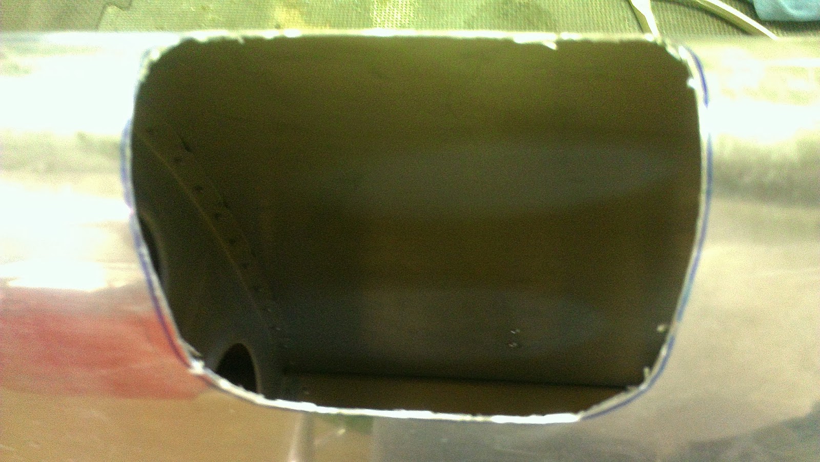
After marking the holes, I checked, checked, and rechecked my measurements. I couldn't imagine the agony I would experience if I cut holes in my wings in the wrong place! Once I convinced myself it was correct, I cut the holes with my dremel  tool. It was a lot easier than I thought it would be.
 
Then I ground the cuts down to the marks and sanded them smooth.


Then I installed the lights.
 
Then I installed the Ztron strobes and position lights in the wingtips.
 

Wednesday, May 1, 2013

Mounting Empennage, fuel tanks.

 Mounting Empennage, fuel tanks
48 Hours  
I mounted the horizontal stabilizer and elevators on the fuse. I actually spent about a half a day leveling the plane in all directions. Measured as per plans. Mounted horizontal stab with 0 deg incidence. I have three levels in my shop and I used all of them. A man can drive himself crazy trying to get everything perfect. Every level seem to be just a hair off of each other.

Setting the 0 deg incidence with the tooling hole in the rib as per plans.
Double checking 0 deg incidence.
Drilling holes! No turning back now!
It is not pictured, but I also temporarily mounted the elev and installed the pushrod. Plans said to mount the tips so I did.
I did not have this piece, F-781. It must have been on the original empenage I sold to Sweetwater guy. I was tempted to fabricate it but as it is such an important part, I ordered it.
I got the vertical stab mounted. I made sure it was perpendicular to the horizontal  stab and put a straight edge behind the hinge brackets and got them straight.
Mounted.
Thats me.
Temporarily mounted the rudder.

Installed rudder tips.
Removed the rudder several times adjusting the rod end bearings until I got it all right.
Built a mounting bracket for my Z-tron strobe tail light.
I cut down and shaped the fairing to have clearance over my tail wheel spring mount.
Epoxied the bracket on the fairing then mounted the fairing on the rudder.
Riveted the fairing in place.
Started working on the notorious empennage  fairing. Actually mine was the original Vans fairing and it wasn't to bad. First I mounted the lower aluminum fairing and riveted them on. I sanded and heated the fairing shaping it to fit closer. After about two days working on it I decided it was good enough.
I put a light behind the fairing and drilled and installed all the nut plates the plans called for. I ordered tinnerman washers to go with the #6 stainless screws.
I did not like the rudder stops that came with the project. I researched and built an internal rudder stop out of 1/2" thick nylon.
It looks nice and after several fittings I got exactly 1 1/8" clearance from the elevator with full deflection of the rudder in both directions.
 On to the fuel tanks. I installed the anti rotation brackets on the 3/8" bulkhead fittings. I also installed a fuel return line in each tank in case I ever needed them. I threw away the cork gaskets and prosealed the whole thing up.
This is the special tool I used to drill through the bulkheads to the last bay for the fuel return line. Being a farmer for 22 years comes in handy when you have to build a tool. I put grease on the bit and cleaned it often while drilling to keep the shavings down to a minimum.
I lost the pictures I took of my tank testing with my homemade manometer. The manometer was really easy to fabricate and worked really well. I connected a 1/2" vinyl  tubing to the fuel fitting and plugged everything off. I then put 32" of colored water into the "Manometer", 30"+- put 1 psi inside the tank. The tanks fluctuated a couple of inches during each 24 hr test and one tank leaked down at first but held good after I cleaned the fuel cap and lubricated it slightly. I also tested the tanks with soapy water.