Hours 102
Total Hours 1085
One of my biggest problems and what I have learned to deal with somewhat is multi-tasking. I have always liked to finish one thing before starting another but that cant be done with this airplane. I need to finish the baffles before I can finish wiring the engine. Cowl before the baffles. Spinner before the cowl, and so on. The engine wiring, baffles, and cowl all have to be completed together. This means I have parts scattered all over the hangar waiting for their turn to be installed. I have ordered certain length bolts and various hardware, and by the time they come in, I have a hard time remembering what they were for because I have moved on to the next part of the build! I hope to be clearing some of this up in the coming months. I have been reading a lot and planning my attack on the Baffles, so I began by cutting out the new spinner for the prop which needs to be removed for easier access to the baffle work ahead.

Then I rigged up a pencil on a stick to check and make sure the spinner was even and not wobbling when spinning. I pulled the top plugs and hit the starter and watched the pencil marks. I drilled the holes thru the spinner and rear bulkhead after getting it good and straight. Later I plan to mount this spinner without any screws showing. It is a modification I have read about on VAF.

I then unmounted the prop and began the baffles. I had been studying this operation for several weeks so I felt fairly confident. Since the Lycoming IO-360 is an air cooled engine, and the RV7 is a tight cowled design, forced cool air needs to be passing by the cooling fins of the engine while it is operating. Air enters the two holes in the cowl on either sides of the prop into the top area that is separated from the bottom area inside the cowl by the baffles. This creates a high pressure side on top of the cylinders and a lower pressure side on the bottom of the cylinders. This causes forced cool air to pass in between the cylinders and thru the cylinder cooling fins and exits out the bottom cowl. This, hopefully, keeps the engine operating temperatures in the green. I fitted all the baffles and skipped the oil cooler install for now. Before I knew it I was needing to configure the "snorkle" for the airbox filter and horizontal induction into the left intake ramp.

This is the "snorkle" kit from Vans.
 | ||||||||||
I found that a 2" PVC collar would fit into the fuel servo after
grinding the edges off slightly. Then I wrapped it with duct tape to
center the snorkle when it is mated with the servo.


I need the fiberglass snorkle to come up from the servo to the left inlet ramp and then form a housing for the air filter. This takes a lot of thinking. Since there are so many different engine combinations for these planes, Vans has generic instructions and you have to figure out what is best for your situation. I put the bottom cowl on to trim the front of the air ramps.
 | |||||
I made a template from copy paper by holding it up against the servo and tapping it with a rubber hammer to create a out line for the holes needed in the snorkle.
 |
I then drilled the holes and cut the snorkle to shape.
 |
 |
I cut out the ramp.
 |
Unfortunately, I realized the filter would be located farther to the outboard side of the engine than what I would like. I researched the matter and found out that the snorkle is designed to go on the IO-360 angle valve engine which is a little wider than my IO-360 parallel valve engine. The only way I can get the filter over where I want it is to cut part of the snorkle and shorten it then re glass it all back together. I decided to take the route several other builders before me did and just leave it where it is. It will not effect the performance at all, I just had it in my mind that when I looked through the inlet hole, I would see the whole filter sitting there right in the center. It bothers me but I will get over it.
 | ||||||||
This is my bending brake. I am forming a plate to go over the air filter to secure it in place.
 | ||||
Here is the plate installed over the filter. The bend is on the outboard side and it will screw into the #2 baffle. I dimpled all the holes and installed nut plates into the filter box built out of angle. The angle was then riveted to the fiberglass snorkle. It is built so you can remove the filter without removing the cowl but after installing the top cowl I realize you may have to be a contortionist to accomplish getting the screws out!
 | |||
I thought I would get by without doing any surgery on the snorkle but the alternator bracket was almost touching the snorkle so I cut out a portion of the snorkle to clear the bracket.
 | ||||||||
Unfortunately I found out what a dremel tool with a multi purpose cutting bit can do when it gets away from you! I spent 15 minutes of my precious time cleaning up DNA all over the workshop. At least I will not have to worry about this fingernail getting too long any time soon!
 | |||||||||||||||||||||||||||||||||||||||||||
After I stopped the bleeding, I glassed over the hole with 4 layers of 8oz cloth. Then I sanded it smooth later. |
 sd sd |
I then installed the alternate air door as per Vans plans. I mixed up a batch of flox and blended the opening to the rest of the snorkle. The alternate air door is opened from a control cable in the cockpit in the case of ice or snow blocking the air filter.
 | |||
 | |||
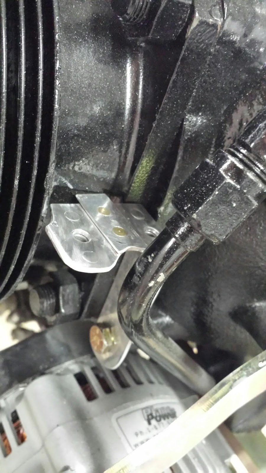
| I worked on modifying the point where the right air ramp mounts to the engine block. The plans called for taking the constant speed prop oil line loose and fitted thru a hole in the ramp. I cut a slot in the ramp so the fitting would not need to be taken loose every time the baffles are removed. A rubber grommet goes around the pipe at final assembly. |
 |
I built the air dam gusset to go onto the right ramp and riveted it in with flush rivets.

 | ||
 |
 |
I used two 2x4's to space out the cowl. I cut an aluminum spacer and drilled a hole allowing for the width of the boards plus 1/2" with a hole drilled in it. I inserted a fine point magic marker in the hole then reached inand marked the baffles all around. The goal is to have a 1/4" gap between the top of the baffles and the cowl.

 | |
After confirming I had trimmed just enough to get the top cowl on, I did the paper clip trick I had read about. I put paper clips all around the baffles then lowered the cowl on. The top cowl pushed down the paper clips to the point where I could measure the gap I had. I then added what I needed for a total of 1/2" of gap.
 |
I then went to work on the oil cooler installation. I mounted it as high as possible so the #4 cylinder would block less air to it.
 |
I had to quit at this point and get ready to go back to work. I put in 85 hr building the baffles and still need to add the baffling to the top to seal them. Then I will probably paint them as it looks like I drug them behind my pickup for a hundred miles! I started my mornings at 3AM and worked till noon this month to avoid the July heat in the hangar. There was a 4 day lake trip included in the two weeks I was off but to be honest, I needed that break. I didn't get as much done as I would have liked but I got some pretty big boogers behind me. I will now work a week and then go to Oshkosh for my first trip to Air-venture! I hope to meet and talk to other RV builders there and meet some of the people (venders) I have been supporting these past two years. I also hope to make a decision on the paint that I will use after seeing all the home builts there. I'm EXCITED about that trip!


