Hours 89
Total Hours 851
I had a good two weeks at the rig without too many problems so I had some time to study up and plan the things I needed to work on to get the engine mount, landing gear, and engine mounted during my April building session.

The first order of business was to finish up my wiring as best as I could before mounting the engine mount and landing gear as that would raise the fuselage about 12" higher. I wired up my P-Leads to the ACS ignition switch. These are actually wires that ground out the magnetos in the off position. The switch also grounds out the right mag in the start position so the impulse coupled mag on the left can start the engine in a slightly delayed timing so the plug will fire on the down stroke. I also wired the P-Leads to the Dynon Skyview Network so that it can give me the engine RPM on my effis. I used the solder sleeves to connect the shields.

Since this is all a little confusing so I double checked my P-Leads to make sure they were grounding in all the right positions of the ignition switch. We wouldn't want the mags to be hot when they are not supposed to be hot! After confirming I had wired everything right, I re-installed the ignition switch to the panel.

I also decided to wire my panel dimmer light and my baggage compartment light to a isolated circuit coming off the battery. I used a 10 amp inline fuse for this as it came off the battery. (Not Pictured) I didn't want to have to turn on my master switch just to load some baggage and get ready to fly. Then I started a two or three day process of cleaning up my wire runs behind the panel and installing plate nuts and adel clamps to secure all the wires. I used about 1000 cable ties bundling wires only to cut them off and start over when things didn't look right. This process was very frustrating! I had to walk away many times and calm myself down. I believe my wiring runs are my weakpoint on this whole project! I wished I could just start over but I know I cant.


After a few days of fighting the whole process, it gradually started looking better. I originally planned to have all my wires under all the sub panels so I could take the entire harness out if I ever needed to. In reality, that is probably a pipe dream as there are so many wires connected to so many things. I could still do it if I had to but the big problem is the shielded wires! They would be tough to splice.
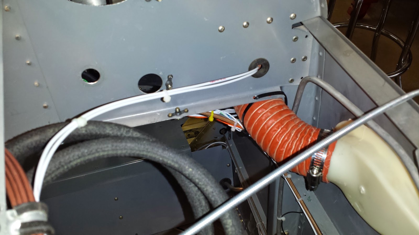
These two P-Leads are the only ones passing thru a hole but I wanted to keep them away from my audio wires. I installed the scat tubing from the vents to the Stein vents on the panel. This was not nearly as hard as I thought it would be. It was nice to get a break on something after the wiring headache!

Moving on to my fiberglass canopy fairing, I peeled the peel ply off and put a application of Super Fill on and let it cure. I sanded that down smooth.

I had layed the piece up earlier from 8 layers of cloth with some micro between the 5th and 6th layers to make the transition. All this was layed up on the canopy and fuselage on a layer of packing tape that had 5 coats of mold release wax. The part popped right off and I was thrilled! I had been dreading fiberglass work for a long time and it was great to accomplish this. Of coarse there is a ton of work left to do on this part!

After trimming up the part, I shot it with primer, found all the pinholes, sanded, thinned some Super Fill and filled pinholes, sanded, shot with primer, and repeated this process about 5 times! It looks great but I still have a few pinholes! I'm studying about these pinholes and will come back to this.....but I am so thrilled with this part! It seals so close all over and fits so well! I cant tell that the canopy was a little higher than the fuselage or the side was a little inset!

I ran the heater cable according to the plans. I bought the stainless steel door from ACS so the large hole will need a B-nut and not the z-bend Vans recommends.

I installed the sensor manifold, 60 amp ANL fuse, battery ground cable, and several firewall plugs. I sealed everything up with 3M Fire Barrier+ 2000.

The throttle and mixture holes were made by the previous owner for a
carb engine so I left them there and will try to utilize them where they
are without putting more holes in the firewall. ( I later learned that
the best place to run these cables is underneath the sump of the engine
because I'm using the Vetterman 4-pipe exhaust set up. This worked great
with the holes where they are) Also as you can see, the fuel fitting is a few inches lower than the fuel injected plans but I believe it will work fine. Not having the crossover exhaust is really going to work in my favor.

I installed the platenuts for the manifold pressure hose then clamped the hose on with the adel clamps in the firewall forward kit. I also installed the second firewall pass thru on the left side. I then lifted the fuselage up and took off the stand that I had built out of 2x6's....Its time to get that mount on!

I mounted the engine mount. It was difficult as the holes were already drilled for the previous "nose dragger" mount that I had taken off. But both mounts are designed for the same hole pattern. The bolts were tough to get in. Luckily I had some old bolts that I could use to help line the holes up. I torqued them to 190 inch pounds and installed the castle nuts and cotter pins. These six little bolts are mighty important as they will have 180 horses pulling on them!

I installed the wheels on the landing gear legs, they were already assembled by the previously builder but I took them apart and repacked the wheel bearings. The big surprise was how hard the left leg was to get into the engine mount socket! This turned out to be an all morning fight! I removed it several times and cleaned more and more powder coat off the leg until it finally gave up and slid into place. I coated the inside areas with wheel bearing grease to inhibit corrosion. I guess it is better to be tight than loose as the one bolt controls the amount of toe in of the wheels. I fought that one bolt for a couple of hours before I realized the inside hole has to be match drilled to the leg and outside hole! After I match drilled it, it was still tight but I got it in. The plans call for a nylock nut but I have ordered an all steel locking nut to put here. The red tape is a reminder that the nuts need to be replaced and torqued. Now she's standing tall!

I really lucked out getting my engine ready to mount. I had read of others that battled the "Dutchman" as my daddy would have called it, for ever! It is a 1/4" pipe plug with an Allen head hole. I heated it a little and it broke loose right away! I installed the bushing and the AN822-4 elbow. This is where my oil separator will return the oil to the crankcase. I wanted to get this done before the engine is mounted.

Installed the oil temp fitting with a new crush washer and safety wired it. The breather fittings were left as was from the previous installation. The mechanical RPM cap is installed and I later safety wired it. There is a steel AN823-4 just under the piece of duck tape. This is where the previous install connected the oil pressure hose. Vans plans call for a different place to get oil pressure and to use a fitting that is restricted. I could not get this "Dutchman out!" I finally ordered a steel flair cap to cap it with and installed Vans restricted fitting as per plans.

I checked a rechecked the plans and various build sites to make sure I didnt need to do anything else before mounting the engine. I reread the write ups on mounting the engine and Vans instructions. I raised the tail.

I layed out the Lord mounts and studied SK-90A. I got my lift all ready. I ignored all the suggestions to get some buddies together to help me and decided to do it alone the next morning. If it was too difficult, I could get my wife, Nancy, to help. I usually work best alone so I can take time to think things out. I got up early the next morning and mounted the engine!

I didnt take any pictures. I took my time. I lifted the engine with the lift and maneuvered into position to get the upper right bolt in first. This bolt took the longest as I didnt know how to maneuver the engine to get the results I wanted. I finally got the bolt in and tightened it. The upper right bolt took some time but I had a little experience now. The lower right bolt popped right in and surprised me! I did have to loosen the top two bolts first. I had to manhandle the last bolt but it didn't take half the time the first bolt did. What helped me the most was inserting a smaller bolt with a flat end on it (no threads) and feeling to see which way the biscuits needed to move to line up with the engine. It took me three hours to have the engine mounted. Half of that was torquing the nuts and installing the cotter pins. I torqued the nuts until I felt them bottom out just like Vans instructions describes.

Needless to say, I am thrilled! I know I have got a long way to go getting everything hooked up, but my project really looks like an airplane now!

I decided to spend some time trying to figure out where I want to mount and run fuel lines, engine controls, and electrical connections. here I am looking at the fuel servo deciding where to mount the red cube fuel flow analyzer.

I reconfigured the spider to mount on the right side of the engine. I am replacing the injector lines later after finding a cracked nut on one of the lines.


The Manifold pressure AN4 bulkhead fitting connects to a short piece of 1/4" flared alum tubing and nut. From there I used a piece of tygon fuel tubing to connect to the MAP transducer. I wired it in and checked my MAP on skyview and it showed 27.3 inches so its working. I hooked up the oil temp and oil pressure and they showed up on skyview after I grounded the engine. Of coarse I had to unbundle a lot of wires so I could do some wiring but the extra height of the fuselage was not as bothersome to work on as I thought it would be.

I decided to mount the red cube on the firewall like so many others have done. I built this mount and ordered the right length bolts to install the cube.

Finally, I installed the Vetterman 4-pipe exhaust system. I know I should have waited until I built my throttle and mixture cable brackets but I just count resist. I torqued the exhaust flanges. My fuel line will come off the red cube on the firewall and enter the left side of the servo. (Left side looking forward from the cockpit which would be the right side of the picture.) The fuel line will leave the servo on the right side and go up to the spider. Both throttle and mixture will come in from beneath the sump. The mixture will not need the bell crank from Vans and will hook to the mixture control arm direct. This solves the problem of the mixture arm hitting my sky tech starter. All it requires is a longer mixture control cable and I will need to build my own cable brackets. I measured and ordered my fuel lines from TS Flightlines. I measured for control cables and will try to come up with the right cables to order....It's been a good two weeks and I am back to work.
No comments:
Post a Comment